
How to use automation to improve productivity and quality in your rolling mill
Automation directly impacts long product rolling mill productivity and product quality. This paper will discuss Russula’s latest technical developments in optimizing rolling mill control.
Background
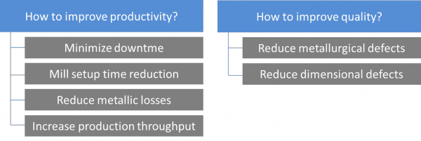
In order to meet market demand, rolling mill requires high levels of productivity while fulfilling stringent quality standards. The rolling mill control system plays an important role in ensuring the correct operation of each link in the equipment chain to achieve the highest sustainable production rate without compromising quality.
Productivity can be defined in many ways, for instance, as the amount of output per unit of input obtained by the utilized resources, and can depend on many factors such as facility layout, pass design, level of automation, state of the equipment, operational staff training and maintenance. In a steel production facility, productivity can be measured in terms of the tons of steel produced divided by the number of employees or employee hours. The tons of steel produced must comply with the steel grade quality standards to be commercial product. In effect, Productivity is a measure of the Efficiency of Production.
This paper will focus on how a rolling mill can increase the productivity of a mill and improve product quality using automation.
Identifying recurring mill losses
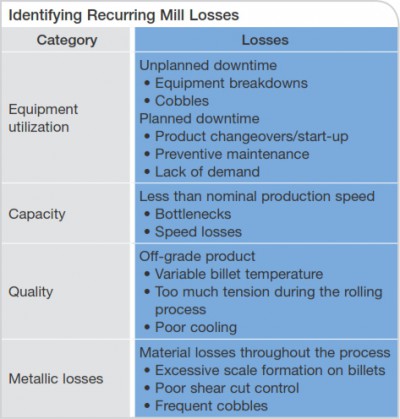
In order to understand how to increase the productivity and product quality using automation, first it is necessary to identify the typical failures in a mill that cause below nominal production rates, downtime, off-grade steel and rework . These are summarized in Table 1. Although steel is one of the most successfully recycled materials in the world, rework has a cost; therefore cobbles, scale and excessive shear cutting can still be considered as metallic losses and should be reduced.
Utilization losses are those that prevent equipment utilization during the calendar time available. They include non-planned downtime, planned downtime for maintenance and downtime due to lack of demand. In this category many mills may use the term availability losses, which are those that prevent equipment utilization all the time that it is allocated to production. The availability of equipment is reduced by downtime spent on product changeovers, restarts after a change and unplanned sporadic equipment failures.
Losses due to poor performance are the factors that prevent the rolling mill from taking advantage of its full capacity. Among the most common losses are reduced production rates, cobbles, equipment failures and rejecting off-grade product as unfit to be sold.
Minimize Downtime
It is very important to anticipate equipment failures, since a good preventive maintenance program will save costs and unplanned downtime. For this purpose, control and data acquisition systems can be really useful. The recording and analysis of equipment consumption, voltage, temperature and vibration data, can predict potential failures, allowing them to be corrected before they impact production. The integration of all sensors, actuators and equipment within the same data acquisition and control system simplifies the recording and processing of data.

It is necessary to identify, for each mill and product, the critical points in the process when the greatest number of cobbles occurs. The tracking system improves the reliability of the mill reducing the cobbles and ensuring the right timing in all the control sequences.
An area where cobbles frequently occur is in the forming of a coil in the laying head of a wire rod mill. The head of the bar, at the time of forming the wire coil, can get stuck in the cooling conveyor rollers. The correct positioning of the laying head synchronized with the front end of the bar ensures that the bar always exits at the correct position, and eliminates snagging at this point.
The correct cut speed and timing is important for the high speed dividing shears. A high performance control system coordinates the shear cut cycle, flaps and diverters, ensuring cut accuracy and repeatability.
In the event that a cobble occurs it is essential to reduce the effects. The automatic cobble detection system will start to cut the remainder of the billet immediately. Compared to manual control, automatic cobble detection responds quicker to a cobble so the operator can resume production faster, especially in the low visibility areas. To avoid creating cobbles the billet head and tail ends, are tracked accurately while being rolled to ensure smooth sequence control. The more automated and stable the mill control, the less possibility for these types of failures, which in turn minimize cobbles.
Mill Setup Time Reduction
Product changeover stops are frequent due to the need to accommodate different production orders. The time to stop, change, start and stabilize the production with the new product can significantly be reduced, automating the processes of change and mill adjustment.

The integration of recipe management and the correct stand change automation, consisting of automatic adjustment of the gap and groove positioning, reduces the time required for product changeovers. It is also important in order to reduce errors by minimizing human intervention during the adjustment.
During the product changeover it is necessary to change all or part of the mill configuration. All parameters and settings are stored in the recipe database. The operator selects the new product, carrying the new settings to the system. Among the settings are gap and stand groove position. Once the new stands are placed, the system adjusts the gap and groove position automatically according to the values stored in the recipe. When the groove is worn and replacement is required, the operator chooses to use the new roll groove and the system automatically positions the stand, aligning the new groove. This automatic process reduces 75% of the time and resources required for changes and adjustments compared to a manual adjustment.
Once the mill is setup and adjusted the next step is to verify that each drive is ready to roll. In this phase is very important to have all the information related to alarms and interlocks. From the HMI it is possible to check each of the roll conditions necessary to connect and start a particular device or area. The correct description of the faults and interlocks, together with a trained staff, greatly speeds up the startup phase, reducing troubleshooting time and breakdowns.
Another really useful tool during this startup phase is the ability to simulate the process using a phantom billet. This feature permits checking the correct function of the sensors and actuators, simulating each of the process sequences. The phantom billet simulation greatly reduces the cobbles during the startup of a new product.
Following the adjustment phase, starting and mill simulation comes the stabilization phase which can be defined as the time it takes to reach nominal production output after a mill change. While rolling the first billet, it is necessary to check for any problems in the guiding and if all the mill adjustments are appropriate. The control system, based on the information received from the field sensors, readjusts the reduction factors, according to the mill configuration. The main objective is to minimize tension along the mill and reach nominal production quickly.
Reduce Metallic Losses
Metal losses are waste material produced along the rolling process that essentially consists of scale formed in the furnace, cobbles and the head and tail cuts of the bars. These losses affect the process yield.

The factors that influence the scale formation are the temperature and the time that the billet remains within the reheat furnace and the furnace atmosphere, particularly oxygen. Correct control of the air-gas ratio in the furnace and implementation of control strategies, adapts the temperature to the rate of production and type of material inside the furnace, thereby reducing scale formation and hence metallic losses.
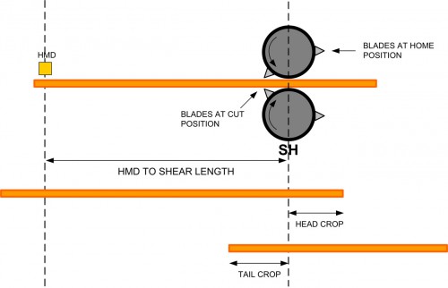
The hot rolling process causes the head of the bar to be deformed while rolling reduction occurs. To avoid problems in the guiding it is necessary to blunt the bar in each of the shears. Precise control of the cutting cycle optimizes the cut length reducing scrap significantly. Using a fast control system for the shears permits accurate tracking and precise synchronization of the cut cycle. All the cuts are measured in time, compensating the reaction time delays of the drive-motor group.
Increase Production Throughput
Mill performance is affected by a reduced rolling speeds, bottlenecks and cobbles in the process. The correct mill adjustment and the performance of the control system play an important role in the stability and speed of production, but another very important part of the control system is material tracking.

Tracking is necessary for the proper operation of tension control, loop control, cobble detection, shear cycles, etc… To easily track the material, the main sensors used for detection are the HMDs and the torque-motor of the stands. Tracking material is also used for interlock sensors, avoiding false detections. Proper operation and placement of each of the sensors along with the good performance of the control algorithms permits high-speed steady rolling with minimal gap between billets. The perfect coordination between material tracking and cascade speed control system reduces the number of cobbles and thus reduce losses due to poor performance.
For each product, there are factors that prevent increasing production speed. Such characteristics include the necessary cooling time, the performance and power of the main drives or the maximum capacity of the reheat furnace. A mill must be treated as a chain, in which the weakest link determines the maximum production. Identifying what equipment is the bottleneck in your rolling mill and developing a preventive maintenance program to keep the mill running as long as possible will increase mill efficiency.
The cold shear cutting area and the finished product handling can become bottlenecks in the process. The proper design of the area, positioning of the sensors, together with the correct automation of the sequences allows reducing these bottlenecks.
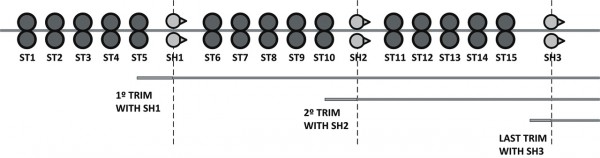
The optimization of the divide shear cut improves material handling in the cold cut area. This method consists of chopping the rest by one or several shears so that the last bar always has an exact multiple customer divide length. Thus, the short bars that hinder production are avoided in the cold cutting area. When the rest is removed, the mill´s metal yield improves, not rolling the useless material.
An improvement to this method is the option of redistributing customer length pieces among the bars. This advanced optimization consists of an automatic calculation of the dividing cuts. The calculation distributes the material, by taking pieces from previous bars to complete the last bar length if it is too short. This optimization reduces metallic losses when the remaining metal bar is too short to be handled by the cooling bed, also avoiding having to chop the whole rest of the bar.
Reduce Metallurgical Defects
Metallurgical defects are all that cause the final material to not comply with the mechanical properties and structural requirements. Metallurgical properties depend on the proper and uniform heating of the material, rolling without tension and the appropriate applied cooling.
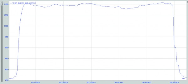
Adequate combustion control and a heating mathematical model in the reheat furnace ensures uniform temperature throughout the billet and is very important to avoid metallurgical defects such as surface decarburization or burnt steel.
Heat treatment is one of the areas where the control equipment is critical and affects the final product quality. There are different cooling methods, depending on the product produced and the type of mill. The water boxes and the cooling conveyor are particularly important.
The water boxes are used for cooling the bar in a controlled manner so that the material has better mechanical characteristics. The method involves pumping water under high pressure which decreases the material surface temperature. The control consists of two control loops working simultaneously. The first loop calculates the water flow setpoint needed based on the measured temperature of the material at the exit of the water box. The second loop controls the water flow based on the setpoint of the first loop.
At the wire rod mill outlet, the cooling conveyor consists of several roller sections with fans installed on the underside. Controlling the airflow in each of the sections can establish the cooling curve and thus guarantee certain microstructures in the material.
Reduce Dimensional Defects
Dimensional defects are mainly related to the shape and dimensions. Depending on the product rolled there are different defects that cause the shape to not be as desired or the measurements to not fall within the required tolerances. The most frequent causes of dimensional defects are due to poor adjustments to the mill control and tension while rolling.
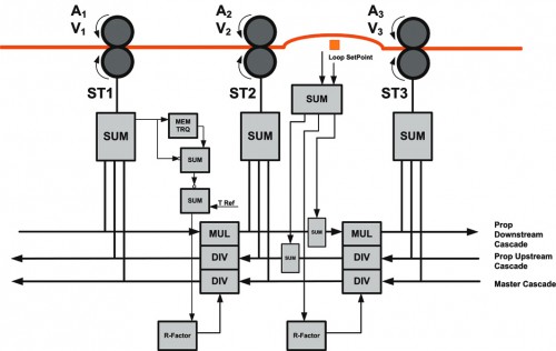
To reduce the material tension along the mill two types of control are applied: minimum tension control and loop control. Each is applied in different parts of the mill. In the first part of mill, roughing and intermediate zone, where the bar section is larger; the minimum tension control is used. In the finishing area, where it is possible to deform the material without damaging it, the loop control is used.
The tension control measures the material tension using the torque applied by the motors. After calculating the tension of the material, the control system adjusts the reduction ratio to minimize the tension according to the setpoint specified by the operator. When the head of the bar enters the first stand, before reaching the downstream stand, the torque is stored. When the bar enters the downstream stand, the current torque will be compared with the stored one. Observing whether the value increases or decreases between two stands determines whether there is a push or pull. The control system acts on the reduction factor correcting the speed difference and thus the tension between the stands.
In the finishing end the material is thinner and it is possible to eliminate the tension with a loop control. Between the stands, a loop table is installed to form the loop when the bar passes. When the head of the bar reaches the downstream stand of the table, the persuader roll rises helping to form the loop. In the table a loop scanner is placed to measures the height of the loop at all times. The operator specifies the loop height and the control algorithm modifies the mill speed in cascade, acting on the reduction factor. Tension free rolling is achieved by keeping a constant loop height.
The good performance of these methods depends primarily on the control system and the process sensors. The correct material tracking is critical for the loop formation and control sequences, especially in high-speed mills. The reduction factor control algorithm is also very important to regulate the coordinated mill speed variation. In the last minute, both the tension and loop control operate on the reduction factor for each of the stands. The control system stores each reduction factor when the process is stable, using it for the next billet. The correct storage of this factor makes it faster for mill adjustments, especially at the start of a new product.
When rolling wire rod, maintaining the correct coil dimensions is essential to comply with quality standards. To achieve correct coil formation it is very important to synchronize the mill exit speed with the laying head speed. The laying head has a great inertia that responds slowly to changes in speed, for this reason it is best to maintain a constant finishing block exit speed.
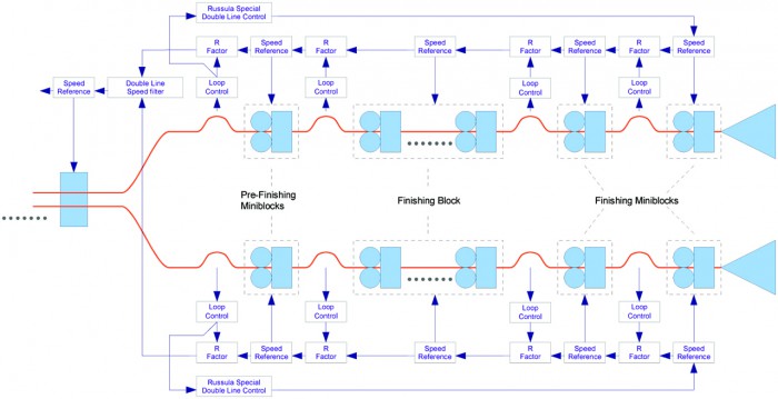
Two strand wire mills deserve special control consideration. In this configuration there is a common area, usually the roughing and intermediate mill, composed of two strand stands, where two billets are rolled simultaneously. After the common area the mill splits into two independent strands. Each of the strands consists of rolling stands, miniblocks and a finishing block. At the output of each block are water boxes and finally a laying head which deposits the wire rod coils on the cooling conveyor. Differences in the adjustments or wear between the two exit lines motivate mills to control both lines downstream. This solution causes the laying head speed to change constantly.
Our proposal is to control the mill upstream with one of the lines as a master. The control compensates for the differences between lines modifying slightly the exit speed of the follower line. This method maintains, during most of the time, a constant speed in both laying heads.
Conclusions
Over the past years Russula has upgraded and replaced control systems for many long product rolling mills. Russula has seen firsthand the typical issues that limit production and affect product quality in bar, wire rod and section mills.
Based on this experience, Russula has developed technical solutions in tension free rolling, shear cut optimization and optimal cooling. By optimizing only the process control, rolling mills are able to improve productivity and production quality, reducing metallic losses and downtimes.