
Control optimization for two strand wire rod mills
Russula has developed an algorithm to ensure correct and uniform coil formation, improving the quality of the final product. The optimization model is configured using a master line and a follower line with upstream control.
In wire rod rolling, speed control is especially critical in the rod outlet section of the finishing mill. In this area, the material has a small cross section area, so it is more flexible, while rolling at very high speeds. Speed corrections can affect the ring dimensions and the mechanical properties (for example, causing stretching while rolling with tension) or defective ring formation at the laying head.
To meet quality standards and avoid potential problems in the ring distributor and the coil forming area, it is essential to maintain the correct ring dimensions. In order to keep a constant ring diameter, the mill product speed must be synchronized with the laying head speed.
Both the finishing block and the laying head equipment have great inertia, which leads to a slower response to sudden changes in speed. However, in simple configurations (such as single strand rolling) this is not an issue, since the product speed is held constant by regulating the speed cascade upstream.
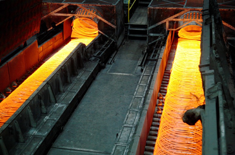
The objective for a two strand wire rod mill is to maximize production capacity. Both strands have a common roughing and intermediate mill, where two bars pass through the stands at the same time. After this the mill divides into two separate finishing lines typically each formed by a finishing block (6 to 10 stands), sometimes also including miniblocks (2 stands), where a single bar is rolled at each outlet. The water boxes are located after the finishing stands on each of these outlets followed by a pinch roll and the laying head, which deposits the rings on the cooling conveyor.
When controlling the speeds of these machines, we found multiple factors causing deviations from the initial cross section area of the theoretical calculation. Among these are the following:
- Roll wear causes reduction variations over time and then differences in the areas between the lines
- Imperfect stand rigidity for the roughing and intermediate mills causes the rolls to separate more when rolling two bars instead of one. As a result this causes variations in the output section of the stock being rolled.
- Variations in the temperature of the bar cause differences in the plastic deformation of the steel, which affect the final dimensions.
All these changes in the product cross section are reflected in variations to be compensated in the control loop or loops before the blocks or miniblocks. This inevitably involves changing the output speed of the lines independently to compensate for differences between them.
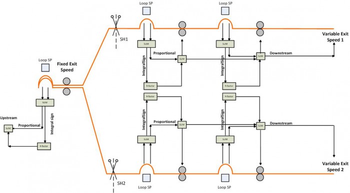
In conventional installations, the adopted solution is to maintain a fixed speed at the last stand in the intermediate mill and perform the adjustment of three separate lines to each other, based on a fixed speed. In the common area regulation is implemented upstream and the two rod outlets are controlled independently downstream. This configuration results in having each line’s loop corrections transmitted in cascade, which strongly impacts the block and laying head speed.
Furthermore this control has limitations such as the fact that both the pinchroll and the laying head speeds change continuously, which may mask response problems in these drives. Having the ability to fix the product speed we can “isolate” these elements and facilitate troubleshooting.
Moreover, the two lines are never actually the same, apart from the roll groove wear and stand rigidity mentioned earlier. Some drives can react worse to process changes, which may have differences in the guiding, or even a loop may exhibit more volatility in one line then the other, and this difference is only compounded with changes in the product speed.
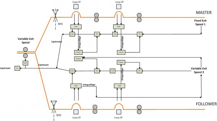
Given these control difficulties and limitations, Russula´s algorithm consists of making a full upstream control to prevent continuous and aggressive speed corrections needed by the downstream control. Unable to maintain two speed controls in cascade that converge at the same point in the common area, a line must be configured as master (with fixed product speed) and the other as a follower.
The system will compensate for differences between the lines and only slightly modify the product speed of the follower. This method maintains, for most of the time, a constant speed in both laying heads.
The algorithm controls the master line as if it was a single strand rod mill. The upstream control loop sends the necessary speed corrections to maintain a stable loop height. The output speed is kept fixed, so that the laying head will not suffer any variation unless the production rate is rising or decreasing.
In the case of the follower outlet, the control is upstream, but while rolling only small corrections are made to the speed of the finishing block to compensate for the imbalances between the two lines. In addition, when there is no bar being rolled in the follower line, its speed remains coordinated with the master´s line by the usual R factors. The reduction factor of the stands, miniblocks and finishing block remains fixed, so that an increase / decrease in the speed of the last stand in the intermediate mill, leads to an increase / decrease in the product speed of the follower line.
This mode of operation involves the following functions:
- Recalculation of the R factor from the first drive of the follower line while rolling.
- Filtering the imbalances between the two lines to generate the correct product speed of the follower line.
In short, variations in the last common stand generated from the master line, will be transmitted to the output speed of the follower line through the loop, except in the case when the production speed is increased, in this case the control system overrides and modifies the speed of the follower without waiting for the speed change to be transmitted by the loop control.
An additional problem with this type of setup is that the loops have severe height fluctuations when a billet enters or leaves the other strand. It is imperative to have stable loop when a front end arrives to the common stands, as these stands will “open” allowing more material through the second strand and this will raise the loops. Likewise when the tail of the bar leaves the common stands, these stands will “close” a bit. It can be dangerous if the loop grows too much since it may make a knot and cobble. In addition, we would be trying to lower the height of one loop and raise the other, which implies opposite effects, taking longer to stabilize both.
To avoid situations like this, the Russula algorithm decreases the set point of the loops when the arrival of a new billet head is detected, to force both loops at once to rise and join forces.
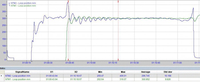
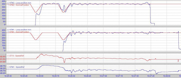
In this exampley ou can see howt he Line 2 loop is formed and when it starts to stabilize,a new bar enters into Line 1 causing an increase in loop height on strand 2. Both loops fluctuate for more than 30 seconds until reaching their reference point.
Behavior of the Control Loops Example
In this example Line 2 is the master and Line 1 is the follower. The moment the head of the billet arrives at Line 2, the loop height set point is lowered, once the loop is formed and stabilizes, it goes to the previous value.
When a new front end on line 1 is passing through the common stands, the line 2 loop height set point ramps down waiting for the line 1 bar to go through the block. When the bar enters the last stands before the fork, it tends to open the roll gap and let more stock go through, this increases the line 2 loop height, as shown in the graph. The system will automatically correct the rise in the loop height by lowering the speed reference of the stand before the fork and this in turn will lower the line 1 block speed. If this was not done the loop would take longer to form since it would maintain the speed relationship between the block and the last stand of the common section. The Line 1 loop height set point also decreases, to return to the initial reference shortly after both loops simultaneously go down hence achieving that both lines need the same effect as the previous stand, it will speed up, decreasing the opposing effects corrections and favoring the stability of both systems.
As a result two effects are achieved, the Line 2 loop does not grow too much when a new bar enters and both loops tend to rise at the same time, which allows them to stabilize in less time.
When the tail leaves Line 2 this generates a pull in the Line 1 due, among other things to a decrease since the common stand closes slightly lowering the loop height for a moment. The control algorithm restores the loop position and stabilizes it quickly.
Benefits of the 2 strand wire rod mill control algorithm
A perfect example of when this type of control is beneficial is the following. In the case when the speed controller drive response of one of the blocks is very slow and fails to follow the reference sent by the PLC. As a result the loop behaves erratically when trying to follow steep speed corrections.
Speed control based on the stock exit velocity at the fork causes speed corrections to happen at the block, and while they are not very steep, the drive still fails to follow due to the high inertia. If we put this problematic line as the master, we ensure that its reference will be a fixed output, thus the follower line will absorb the speed variations, this line has a more stable speed and keeps the two loop heights in the operational window.
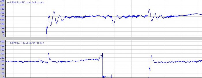
In comparing the two graphs, in the case of downstream control, although the speed in the stand previous to the fork is kept constant, line 2 shows significant disturbances when the loop is formed, since it is not able to follow the necessary corrections to stabilize quickly. The same is true when a bar enters or leaves the other line, even though the only way one strand can interfere with the other is through the increase or decrease of stock that occurs when a bar enters or leaves the common stands.
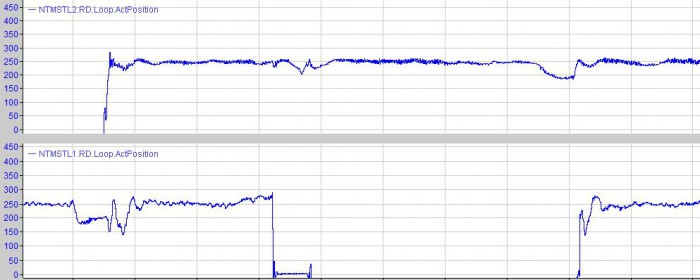
Conversely, selecting this line as a master and changing the reference point allows both loops to be more stable and react to changes in a more controlled manner, since less corrections are sent to the line 2 block, what this block cannot achieve, is absorbed by line 1, which has a faster response.